|
|
|
Информация
От Редакции АТ
В научном журнале Journal of Propulsion and Power прошла рецензирование экспертов и опубликована статья о двигателе EmDrive, работа которого до сих пор не получила объяснения в рамках законов сохранения. В ней сообщается, что EmDrive в вакууме развивает тягу в 1,2 миллиньютона на киловатт. Рецензенты не смогли найти ошибок в конструкции испытательного стенда и агрегата, а авторы работы — обратной силы, отвечающей на развиваемую EmDrive реактивную тягу. У статьи семь авторов — Гарольд Уайт, Пол Марч, Джеймс Лоуренс, Джерри Вера, Андре Сильвестр, Дэвид Брэйди и Пол Бэйли, которые работают в Космическом центре имени Линдона Джонсона.
Вслед за академиками РАН и специалистами комиссии по борьбе с лженаукой мы можем констатировать, что лженаука пробралась в космическую отрасль США.
ABSTRACT
A vacuum test campaign evaluating the impulsive thrust performance of a tapered radio-frequency test article excited in the transverse magnitude 212 mode at 1937 MHz has been completed. The test campaign consisted of a forward thrust phase and reverse thrust phase at less than 8x10⁻⁶ torr vacuum with power scans at 40, 60, and 80 W. The test campaign included a null thrust test effort to identify any mundane sources of impulsive thrust; however, none were identified. Thrust data from forward, reverse, and null suggested that the system was consistently performing with a thrust-to-power ratio of 1.2±0.1 mN/kW
I. Introduction
It was previously reported that radio-frequency (RF) resonant cavities generated anomalous thrust on a low-thrust torsion pendulum [1,2] in spite of the apparent lack of a propellant or other medium with which to exchange momentum. It is shown here that a dielectrically loaded, tapered RF test article excited in the transverse magnetic 212 (TM212) mode (see Fig. 1) at 1937 MHz is capable of consistently generating force at a thrust-to-power level of 1.2±0.1 mN/kW
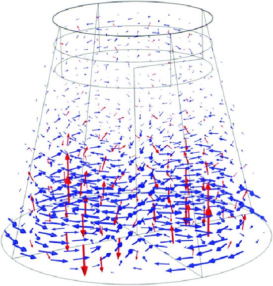
Fig. 1 TM212 field lines in dielectric loaded cavity: red arrows represent electric field, and blue arrows represent magnetic field.
II. Experimentation
A. Facilities
The thrust measurements were made using the low-thrust torsion pendulum at NASA Johnson Space Center. This torsion pendulum is capable of measuring thrust down to the single-digit micronewton level. Figure 2 shows a simple representation of the torsion pendulum’s major elements. The torsion pendulum is constructed primarily of an aluminum structure that is mounted on a slideout table within a 0.762-by-0.914 m vacuum chamber. The chamber is subsequently mounted on a 1.219-by-2.438 m optical bench. The pendulum arm pivots about two linear flexure bearings in a plane normal to gravitational acceleration. For every thrust measurement, a calibration force is provided by means of establishing a voltage potential across a set of interleaving aluminum electrostatic fins [3], with one set of fins on the fixed structure and one set on the pendulum arm. The fins overlap without touching. A calibration voltage is applied to the fixed structure fins, which induces a force upon the pendulum arm fins and an associated displacement that is measured by the system. The electrostatic fins design provides a constant electrostatic force over a reasonably large range (between 30 and 70% overlap, or a few millimeters of travel), so adjustments to the calibration mechanism between test-run data takes are usually not required. Calibration of the overlap/force relationship is accomplished using a Scientech SA 210 precision weighing balance (resolution to 1 μN). The displacement of the torsion pendulum is recorded by an optical displacement sensor, and the steady-state displacement from the calibration force is used to calibrate any force applied to the torsion pendulum by a device under test. The optical displacement sensor can be accurately positioned relative to the torsion pendulum by means of X-Y-Z micropositioning stages. Whenever a force is induced upon the pendulum arm, the resultant harmonic motion must be damped. This is accomplished via the use of a magnetic damper at the back of the torsion pendulum arm. Four neodymium (NdFeB grade N42) block magnets interact with the pendulum’s copper damper angle bracket to dampen oscillatory motion. The magnets are housed in a low-carbon steel square tube to better localize the magnetic field of the magnets in the damper and not in the chamber. Vacuum conditions are provided by two roughing pumps and two high-speed turbopumps, and all vacuum tests are performed at or below 8x10⁻⁶ torr. The high-frequency vibrations from the turbopump have no noticeable effect on the testing seismic environment.
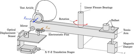
Fig. 2 Simplified representation of torsion pendulum.
All dc power and control signals pass between the external equipment and vacuum chamber internal components via sealed feedthrough ports. Inside the vacuum chamber, all dc power and control signals that pass between the torsion pendulum fixed structure and the pendulum arm are transmitted via liquid metal contacts in order to eliminate interface cable forces. Each liquid metal contact consists of a physical but non-force-producing interface between a brass screw and a small socket filled with Galinstan liquid metal. The test article is mounted on the end of the pendulum arm closest to the chamber door. Test article support electronics (e.g., signal generators, amplifiers, phase adjusters) may be mounted on either end of the pendulum arm. If needed, ballast is added to the pendulum arm to eliminate moments that affect the neutral position of the pendulum arm. After a test article is mounted on the pendulum arm, a typical test-run data take consists of a prerun calibration (using the electrostatic fin mechanism), followed by energizing the test article, and finishing with a postrun calibration and data recording.
Полный текст доступен в формате PDF (1015Кб)
Информация , Measurement of Impulsive Thrust from a Closed Radio-Frequency Cavity in Vacuum // «Академия Тринитаризма», М.,
|
|